Introduction #
The domain model is a conceptual framework that outlines the different entities, their attributes, relationships, and constraints that govern the problem domain of a specific application or system. It acts as a blueprint for comprehending, documenting, and communicating the structure and semantics of the application domain space.
Essential aspects of a domain model include:
- Entities These are the primary elements within the domain. For example, in a banking application, entities might include Account, Customer, Transaction, etc.
- Fields: Characteristics or properties of entities. For example, a Customer entity might have fields like name, address, and phone number.
- Relationships are connections between entities that indicate how they interact or are related to each other. For instance, a Customer may have one or more Orders.
- Inheritance Associations: This refers to the relationship between two entities, where a child entity inherits fields from a parent entity.
Creating a domain model is often one of the initial steps in the design phase of software development. It helps stakeholders understand the system and provides a foundation for the development of the system’s architecture and functionality. This approach is especially prevalent in methodologies like Domain-Driven Design (DDD), which focuses on developing a rich understanding and model of the domain as a core to the software development process.
Application Domain Experts can create the domain model using the tools provided by Wizzdi Cloud as long as the concepts of entities, fields, and relationships are understood. It is easy to apply changes to the existing and deployed App, reflecting changing requirements or a more profound and better understanding of the application domain.
The domain model in Wizzdi Cloud is managed through one or more Entity Diagrams. This arrangement depicts the app’s data architecture and the relationships between different data entities.
Upon finalizing the domain model, the app is ready for deployment. This process exposes a CRUD API, which facilitates the management of the entities defined in the domain model. Any adjustments made to the domain model automatically result in updates to the API endpoints, reflecting the changes without manual intervention. This early version of the APP includes the required API endpoints to manage the created entities.
Users will likely introduce additional APIs, services, and functionalities using Wizzdi Cloud’s built-in tools or incorporate custom code using their preferred development tools. Regardless of the method chosen, updates to the domain model and the corresponding APIs are seamlessly integrated into the app. Wizzdi Cloud maintains continuous synchronization with the developers’ modifications, ensuring the app remains consistent with the evolving domain model.
- Entity Diagrams: Within the domain model section, you can create multiple entity diagrams. These visual representations help you understand and design your system’s core data architecture.
- Creation and Import Options: Entities can be manually created or imported from various sources, such as other projects. Entities can be referenced from other workspace projects or marketplaces you can access.
- Extensibility and Inheritance: An entity isn’t restricted to a standalone structure. It can extend or inherit from other entities, cascading down properties and features from its parent or super-entities. This inheritance mechanism allows for a layered and hierarchical design, minimizing redundancy. Support for mapped Superclasses is provided.
- Relationships: Entities can be interconnected in various ways, reflecting their real-world relationships. Wizzdi Cloud supports diverse relation types:
- One-to-Many: A single instance of one entity relates to multiple instances of another.
- Many-to-One: Multiple instances of one entity associated with a single instance of another.
- Many-to-Many: Instances of one entity can relate to multiple instances of another and vice-versa.
- Backend Representation: Entities typically translate to tables within a database in traditional backend structures for those who want a peek behind the curtain. The relational database used in Wizzdi Cloud is PostgreSQL.
- Relational Database Integration: When deployed, Wizzdi Cloud is engineered to leverage the power of relational databases. So, in essence, each entity you design likely corresponds to a table in this database, establishing the groundwork for your backend’s architecture.

Overview #
Start the domain model editor by clicking on Domain Model in the app’s side menu.

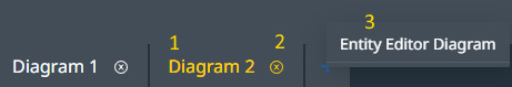
- This is the diagram’s name; you can use #10 to edit the name. The small [x] lets you remove the diagram from the view; the diagram is NOT deleted and is still available when adding a new diagram.
- Add a new diagram; if diagrams have been removed, they appear for selection.
- Zoom out. You can also zoom out using the mouse wheel.
- Restore the view to 100% zoom.
- Zoom in. It’s worth noting that you can also zoom in using the mouse wheel.
- Undo
- Redo
- Auto-arrange the current diagram.
- Make the view larger; the left-side menu is made invisible.
- Rename the diagram.
- Add a description to the diagram.
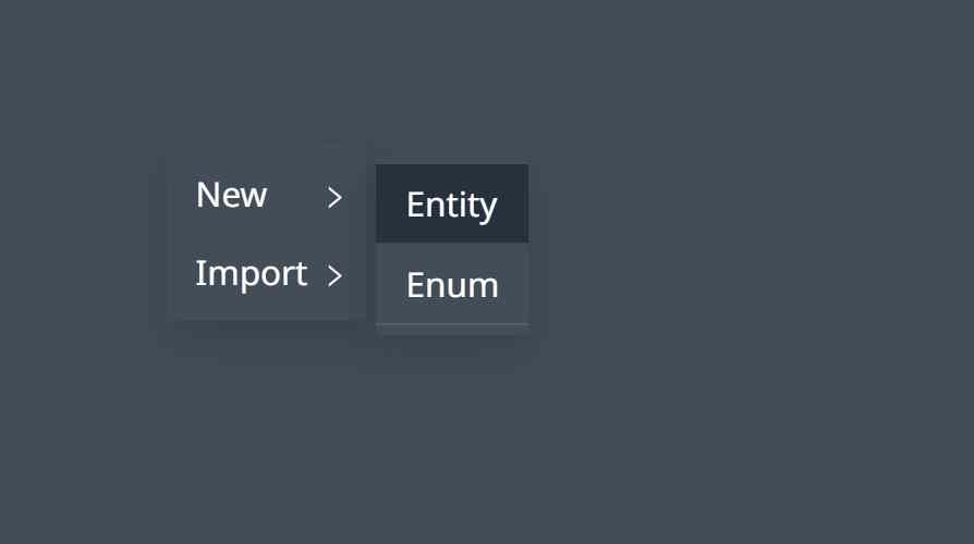
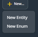
- Add a new Entity.
- Import an Entity or an Enum; Import items from the current or referenced projects into the current diagram.
Entities #
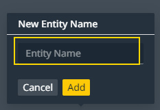
Create an entity using right-click
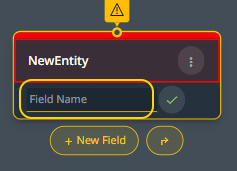
The New Entity has a name field. Entity names must start with a Capital letter. The right-side menu provides a Description field for the currently selected entity.

Once an entity is created, the following tools and actions are available. The same action is often available from multiple places.

- Warning indicator: hover over the icon for more information about the warning.
- Additional actions menu.
- The entity can be renamed by double-clicking on the name; editing is then available. Renaming an entity is also available from the right-side menu.
- New field button. Add a new field to the entity.
- Connect to other entities, which will be discussed later in this guide.
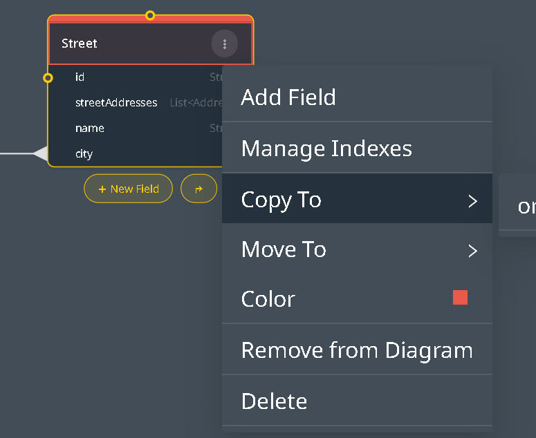
This menu is available from the three dots button on the entity.
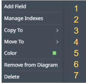
- Add a new field. This option is available from the bottom of the entity thumbnail and the right-side menu.
- Entities can have indexes added to improve data retrieval speed. Refer below for additional information.
- When creating an entity relationship involving entities from multiple diagrams, copying and moving entities to another diagram is necessary. This operation concerns only the arrangement of entities on diagrams.
- Move to another diagram, similar to the previous section, but the entity is removed.
- Change the color of the entity in the top bar. It helps in better organizing the diagram.
- Remove from diagram; Remove the entity from the diagram. The entity is not deleted.
- Delete the entity. The entity is deleted and removed from all diagrams.
Inheritance #
Wizzdi Cloud supports inheritance, a cornerstone of Object-Oriented Programming (OOP). In data modeling and entity structures, inheritance allows one entity to inherit attributes or characteristics from another, establishing a hierarchical relationship between them.
For example, if there’s a base entity named ‘Vehicle‘ with attributes like speed and weight, a derived entity such as ‘Car‘ can inherit these attributes and might introduce new ones specific to it, like trunk size. By supporting inheritance in Wizzdi Cloud, users can create data models that depict these structured, hierarchical relationships, ensuring a more organized and intuitive representation of data. Furthermore, Wizzdi Cloud adeptly manages the underlying complexity of handling inheritance at the database level, abstracting these intricacies from the user and providing a seamless experience.
Furthermore, it’s important to note that inheritance is crucial in reusing domain models you or other users created on the Wizzdi cloud or available from the Wizzdi or other marketplaces. Through inheritance, you can modify and improve upon the original design of these models.
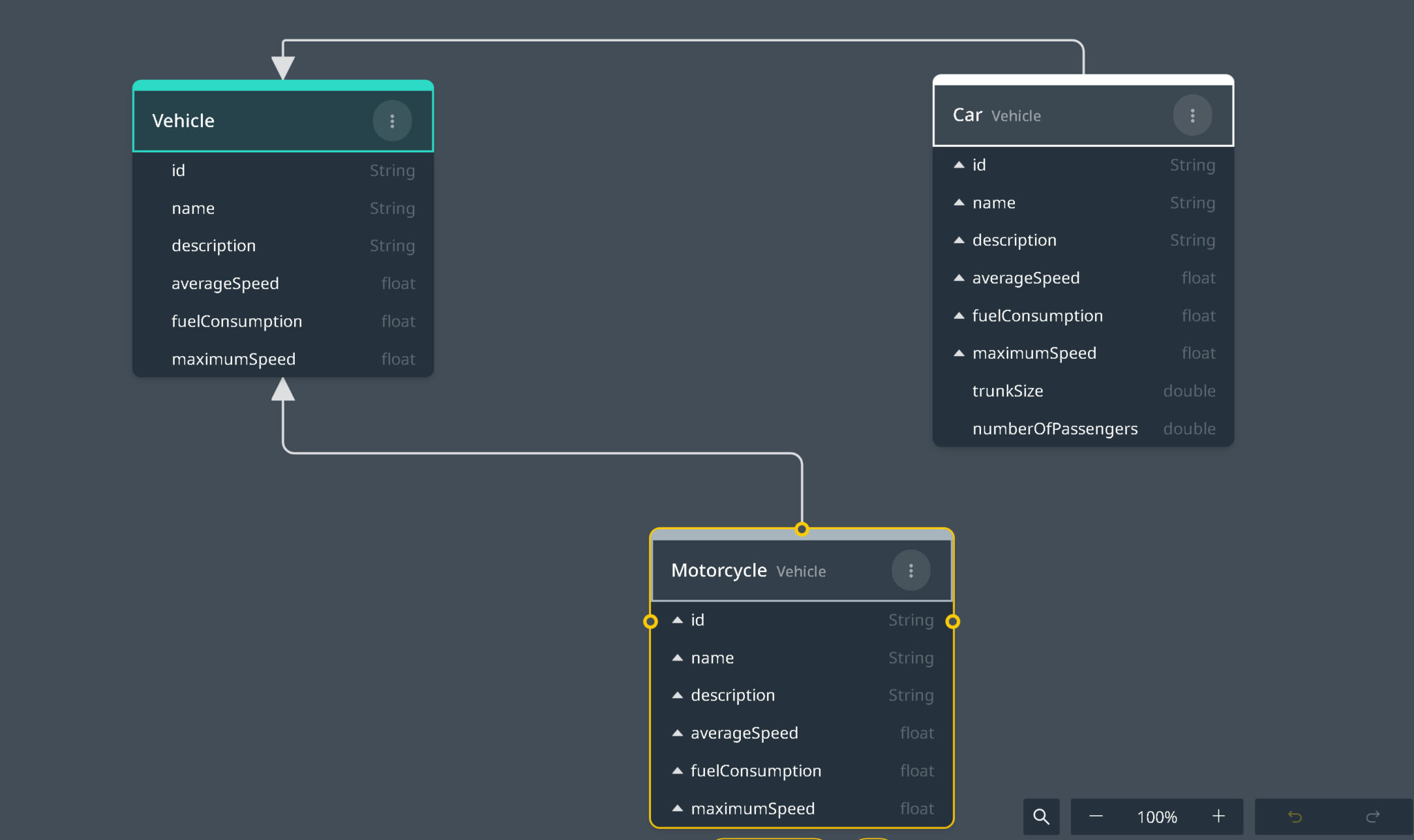
Inheritance example: Vehicles Cars, and Motorcycles
To create an inheritance link between an entity and its Super Entity, select the entity, drag the small circle on top of the Entity shape, and release it above the name of the Super Entity.
An entity can have only a single Super Entity. A single Super-Entity can have multiple ‘children‘ entities.
Click on the three dots menu to detach an entity from its Super Entity. When an entity extends a super entity, all fields from the super entity are automatically inherited and visible within the extending entity. This inheritance can cascade through multiple levels or layers of hierarchy. It’s important to note that once fields are inherited, they become unchangeable on the child entity. To modify these fields, one must navigate to the original super entity where they are defined, even if this means moving up several levels in the inheritance chain.
The parent entity in the inheritance hierarchy can be a Mapped Super Class.
A Mapped Superclass is a model from which other entities can inherit properties and mappings but is not itself an entity. It does not have its database table; instead, it allows its subclasses to inherit its properties, ensuring that these properties are mapped to the columns of the subclasses’ tables. This approach helps define standard fields (like id, name, description, createdAt, and updatedAt) across multiple entities without duplicating the mapping information in each entity class. This option should be preferred if you never need to manage the mapped superclass directly. For example, suppose the Mapped Super Class Base is defined to hold standard fields across multiple entities such as name, description, createdAt, and updatedAt. In that case, there is no need to manage the Base entity directly, as this entity is created only to save extra typing and make the refactoring of standard fields easier.
When a Superclass is not a Mapped Superclass, it and all its subclasses share the same table, with a discriminator column to differentiate between them.
Remove/Edit Inheritance #
Lines connect the super-entity with its children when entities are related through inheritance. These lines can be hidden to simplify the diagram.
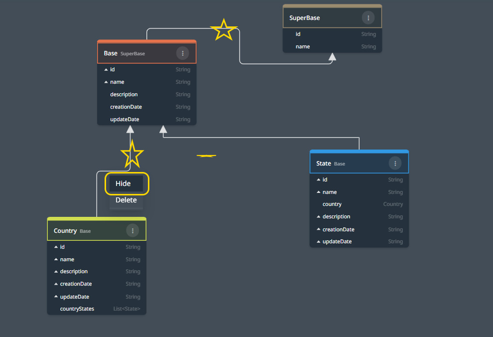
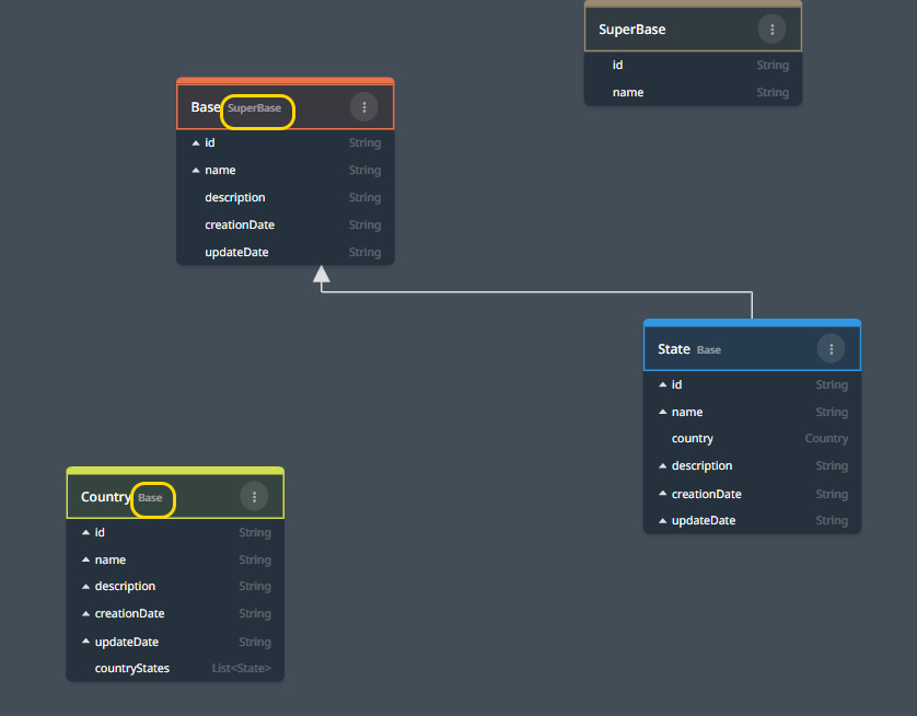
A child entity shows its super-entity to the right side of its name; in the example above, Base extends Country, and SuperBase extends Base. When the inheritance line is clicked, a menu pops up. The inheritance can be deleted or hidden.
All inheritance lines up to the top become invisible when hidden, yet super-entity names remain visible on the entity top bar.
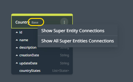
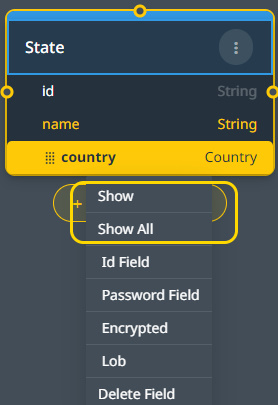
Click the name of the super-entity on the right side of a ‘Child’ entity name to display a menu for showing the inheritance line up to the next level by Show or show all the inheritance lines through the top by Show All.
External Entities #
to import an external entity from a dependency (see project dependencies) by using either the import external button on the right side or by using the context menu on a visible space of the diagram,
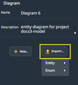
Import an entity or enum
Use Internal to import Entities from the current App.
Use External to import from dependent apps. These are Apps added to the Dependencies section.
Enums #
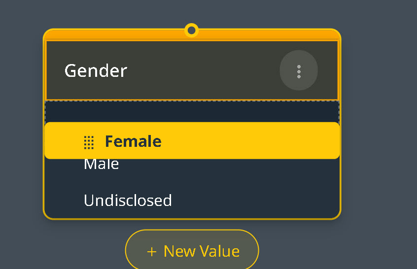
When creating a domain model, we sometimes prefer predefined values over entities. For instance, for Gender, we might list:
- Female
- Male
- Undisclosed
Enums should be utilized in scenarios where the set of possible values is determined at the time of the application’s development, and there’s no anticipation of modifying these values post-deployment. Altering an enum necessitates updates to the application or its underlying code, reflecting a more static or immutable approach to handling certain data types.
Conversely, a dedicated table or entity structure provides a dynamic framework for managing possible values. This approach allows authorized users to add, remove, or modify the values as required without requiring direct App changes. It offers flexibility and adaptability.
Enum names must start with a Capital letter.
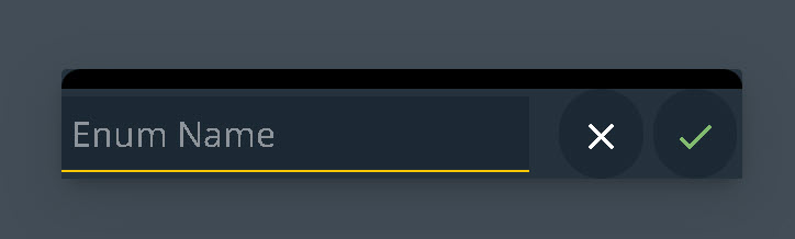
New Enum Dialog
You can add Enums using the button on the screen’s right side area.
Type a capitalized name, click the green checkmark, or hit the “enter” key.
To add values to an Enum, select it and click “add value”. You can continue adding values by hitting the “enter” key after each one.
Enum values can begin with either a capital or non-capital letter.
To rearrange Enum values, drag and drop to a new position.
Importing Enums #
Use Internal to import Enums from the current App.
Use External to import from dependent apps. These are Apps added to the Dependencies section.
Fields #
To add a field, select the entity and click the ‘+New field’ button.
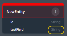
Type the new field name in the text box. Then, hit the ‘Enter’ key if you want to add another field, hit the ESC key to cancel, or click on the green check mark button to finish.
By default, fields are of the String type; this is a text field, limited in size unless the Lob option is used; see fields’ purpose below.
Click on the field type to change the type. Start typing to search for the required type.
Click on the type to change it.
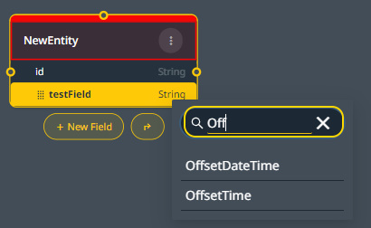
Search for the type and select it.
The field type can be changed from the right-side menu once the field is selected.
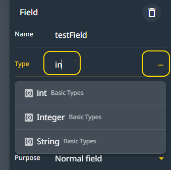
Search for type on the side menu.
Click on the three dots (…) to access a more powerful tool for searching for a type.
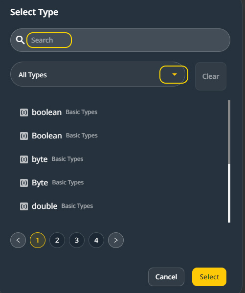
Filter results by type name using the search box above, or use the drop-down to search by type’s grouping or origin.
The grouping includes Basic Types, Entities, Enums, and Types defined elsewhere in the current App or any library or App it references.
Note: other entities can be searched for when searching for a type. When another entity is selected for a field type, a reference to this entity is created. Below, you can see other ways to associate entities by reference.
Note: When adding multiple fields using the ‘enter’ key after each field, the type selected for any field becomes the default for subsequent fields until the type changes. When stopping multiple field entries using the ‘Esc’ key, The default type becomes String again.
Purpose #
Select a field to highlight it, then select the Purpose drop-down on the right-side menu.
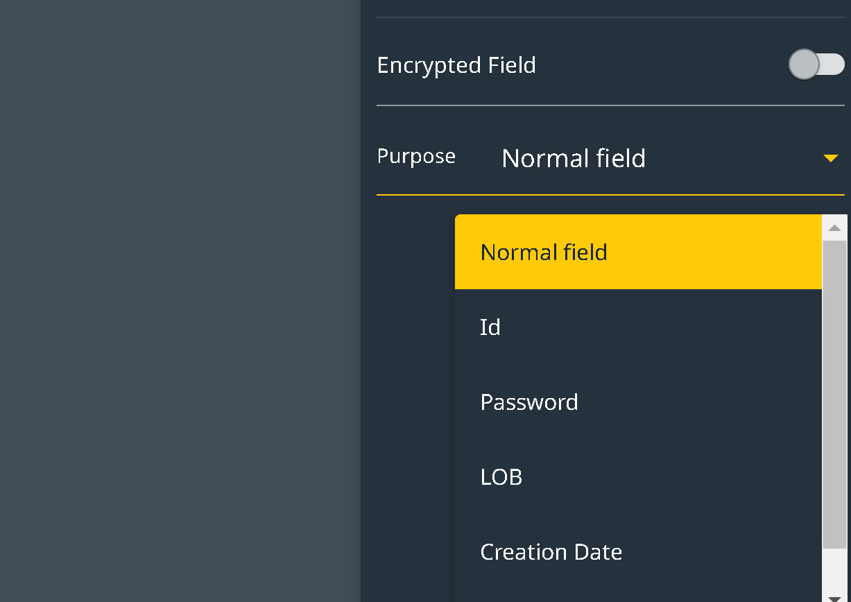
Field purpose selection.
Normal Field #
Most Fields have no particular purpose. There is no need to set a purpose in such a case.
Id #
This is similar to a unique identification number for an entity’s instance. Every entity should have this field, which can be inherited from a Super Entity. See below.
In Wizzdi Cloud, an ID is a String or a long. You can designate any field as an ID field, but only one can be designated as such. You can set the field purpose as an ID by selecting it from the right-side menu or using the “id” designated name.
Password #
The password is stored in an encrypted format within the password field, ensuring it remains secure and inaccessible. This encryption applies when any entity, such as a User entity, is retrieved by a front-end client, and the password field is included in the retrieval. Consequently, the encrypted password cannot be deciphered or used to infer the original password. Furthermore, even if the application operates outside the Wizzdi cloud environment and the database is directly accessed, the encryption safeguards the passwords against any attempts to deduce them.
The type of a Password field must be a String.
LOB #
A LOB (Large Object) field is designed to store substantial amounts of text, significantly surpassing the capacity of standard text fields, which typically cap at a few hundred characters. This makes LOB fields ideal for accommodating large documents, extensive descriptions, or any other form of data that requires more space than what is offered by conventional text fields. The LOB purpose applies only to String-type fields.
Creation Date #
The system automatically records the creation date for any newly created instance when a field is designated as the OffSetDateTime type, and its purpose is configured as a Creation Date.
Update Date #
The system automatically records the last update date for any instance when a field is designated as the OffSetDateTime type, and its purpose is configured as an Update Date.
Note: You must ensure the purpose aligns with the field type, as this isn’t done automatically.
Field Ordering #
 #
#
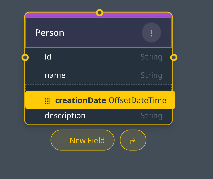
Dragging a field to a new position
To rearrange an entity’s fields, click on each one and drag it up or down to the desired position.
Entity Relationships #
In Wizzdi Cloud’s architecture, entities can be linked using different association types, resulting in diverse relationships and data mappings. Specifically, the available association types are:
One-to-Many #
A one-to-many relationship between entities occurs when a single record in one entity (often referred to as the “parent”) can be associated with multiple records in another entity (referred to as the “children”). This type of relationship is commonly used to model scenarios where an entity needs to be linked to multiple instances of another entity. For example, in a database modeling a library system, a single Author entity might have a one-to-many relationship with a Book entity, indicating that one author can write multiple books. This relationship is typically implemented in databases by adding a field in the child entity that stores the reference to the parent entity’s identifier, establishing a clear link between each child and its parent.
Many-to-One #
A many-to-one relationship between entities is the inverse of a one-to-many relationship, where multiple records in one entity (the “children”) are associated with a single record in another entity (the “parent”). This type of relationship is commonly utilized to represent scenarios where several instances of one entity are linked to a single instance of another entity. For example, in a company’s departmental structure database, multiple Employee entities (children) could have a many-to-one relationship with a Department entity (parent), meaning that many employees belong to one department. This relationship is typically facilitated by including a field in the child entity (Employee) that references the parent entity (Department), thus establishing a connection from many children to one parent.
Many-to-Many #
A many-to-many relationship between entities occurs when multiple records in one entity can be associated with multiple records in another entity. This relationship type represents complex scenarios without a simple one-to-many correspondence between entities. For example, in a university system, a student entity might have a many-to-many relationship with a course entity, indicating that each student can enroll in multiple courses, and a course may include multiple students. A connection entity is typically used to implement this relationship in a system. This entity contains references to the two entities it connects, effectively linking multiple records from both entities and enabling the many-to-many association.
Examples #
In the diagram below, we have two entities, City and State.
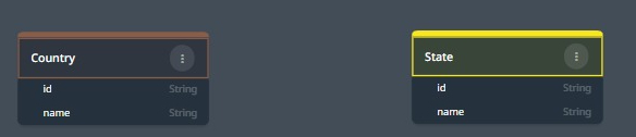
Although a City may reside in only one State, multiple Cities can belong to the same State. This creates a ‘Many-to-One’ relationship from the City perspective, meaning many Cities belong to the same State. However, from the viewpoint of the State entity, it’s ‘One-to-Many’ — one State is linked to many Cities. When defining such relationships, it’s important to establish the association from the ‘many’ side. Therefore, it’s necessary to include a ‘state‘ field within the City entity. Here’s how we can achieve this:
#
One-to-Many #
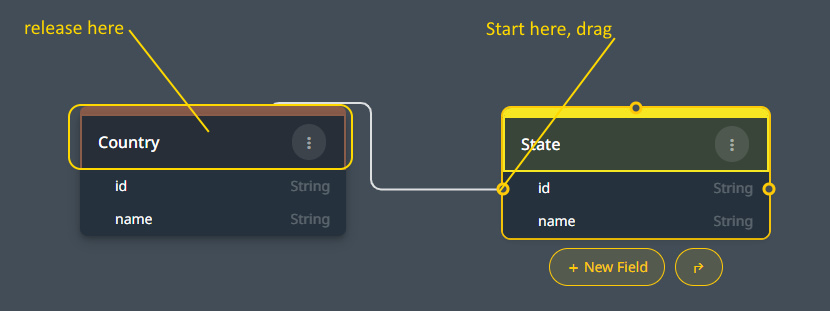
Click on the one-sided entity, which in this example is the Country. We start with the ‘one’ side, but as you will see, the ‘many’ side holds the definition.
Drag the small circle onto the name of the other entity, in this case, the State entity. Release it when the pointer is over the other entity’s name.
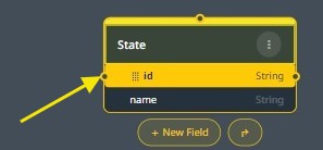
Drag and release from the id field.
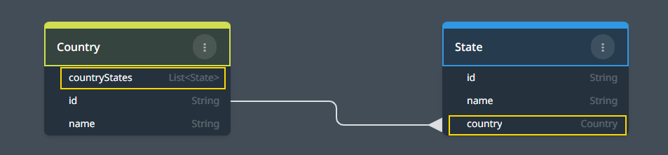
The state entity now has a field named country to indicate the connection’s ownership. A list of State instances has also been added to the Country entity.
When a one-to-one relationship is needed, create a many-to-one relationship instead.
Alternatively, it is possible to create the relationship using the Arrow button.
#
The entity-relationship tool
Click on the 90-degree bent arrow to open an entity search dialog. This should be done on the many-to-one side entity.
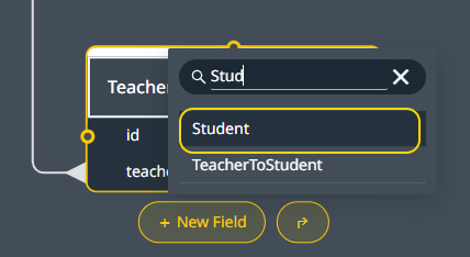
Search for the one-to-many side entity, and click on the selected entity in the above image, the Student entity.
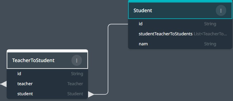
In the many-to-one entity, a new student field is created. in the one-to-many side entity, a List of StudentTeacherToStudents is created.
This field facilitates more flexible joins when using the Custom Query tool. When this entity is retrieved, the list is never populated. The opposite approach is considered inefficient.
Many-To-Many #
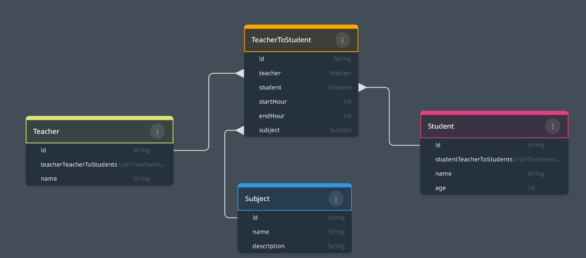
Consider the following entity diagram.
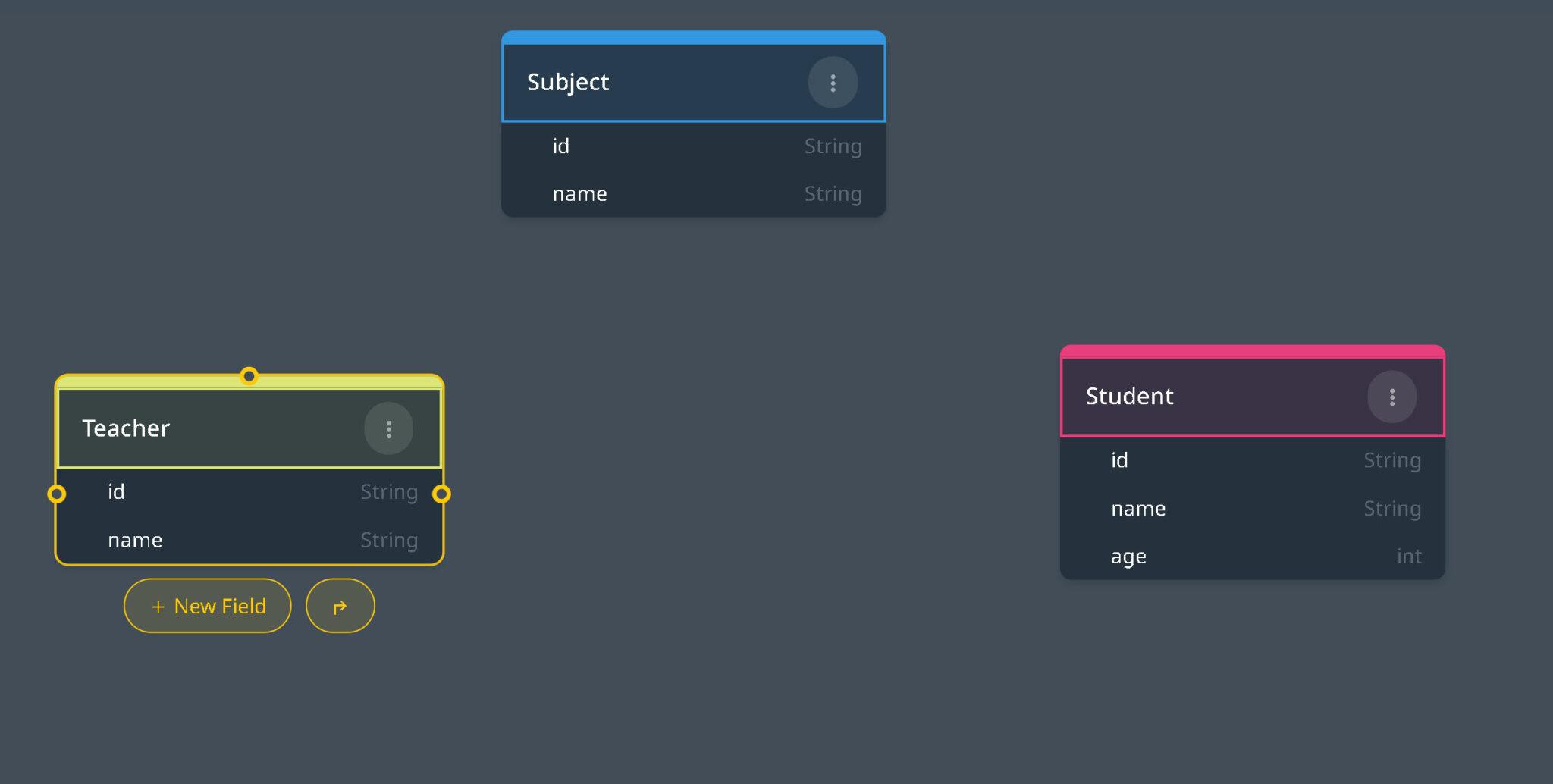
A simplified teacher and student diagram
This diagram illustrates three entities: Student, Teacher, and Subject. A Many-to-Many relationship is formed when a single teacher instructs multiple students, and a student may receive guidance from multiple teachers. In Wizzdi Cloud, you can establish a many-to-many relationship between entities by dragging the id field circle of one entity onto the id field of the other. Drag the small circle of the id field of the first entity (Teacher) and release it over the id field of the other entity (Student) when it becomes selected.
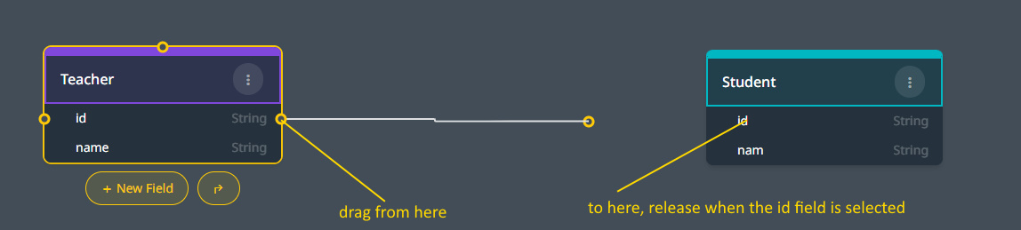
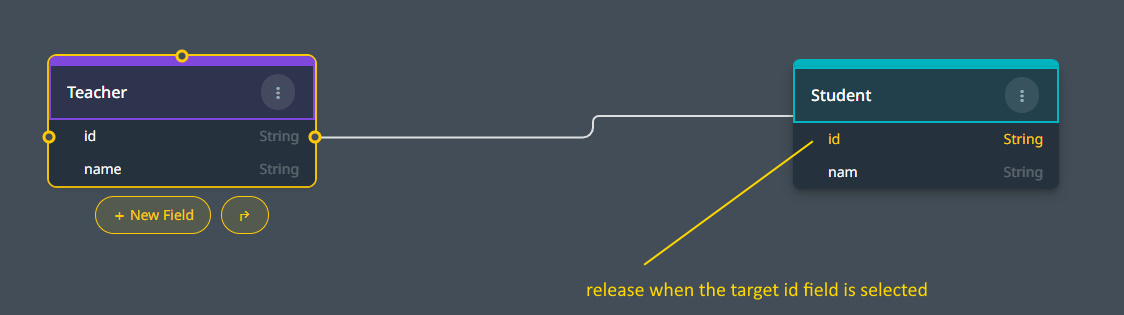
Release when the second entity id field is selected.
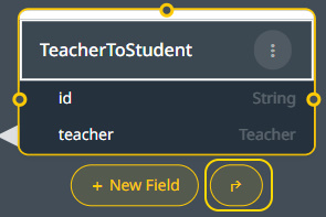
A new connection entity is generated.
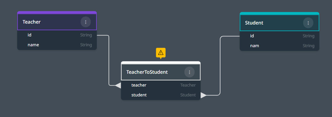
A connection entity is automatically generated when you create a many-to-many relationship between two entities. However, if you prefer, you can create this entity manually and link it to both associated entities as the ‘One’ side. It’s important to note that this connection entity is a primary participant in the schema, not a secondary one. For instance, the absence of a field serving the ‘id’ purpose is indicated by a yellow flag above it.
A common way to improve the information about a connection is by adding extra fields describing the nature or features of the relationship. For example, when arranging a class, it would be helpful to include fields that indicate the day of the week, start time, and end time of the class. So, let’s add these fields to enhance the information about the class. We have already added an entity called subject, which can be dragged (from the id circle) onto the connection entity head to include the Subject in the connection.
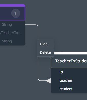
Remove/Edit Relationship #
When hovering over a relationship line, the line becomes emphasized. Click on the line to get a menu for deleting or hiding the line.
If you delete a relationship line, the fields linked on either end of the line will also be deleted.
Hiding lines can improve view clarity by reducing overlaps.
To show a hidden relationship line, access the field on the many-to-one entity and use the available menu to make the relationship visible.
Indexes #
Indexes can significantly enhance query performance in a database by facilitating faster search operations. While it’s common practice to define indexes on frequently queried fields to optimize performance explicitly, it’s not required to manually index fields that are used to associate the Many-Side entity with another entity. The underlying database engine automatically indexes these fields.
Setting an Index on an Entity
Indexes are attributes of an Entity, and multiple indexes can be added. They can enforce uniqueness and may also be composite. Composite indexes are beneficial for data requiring multi-level sorting.
To set an index, select an entity and click ‘manage indexes’:

Manage indexes
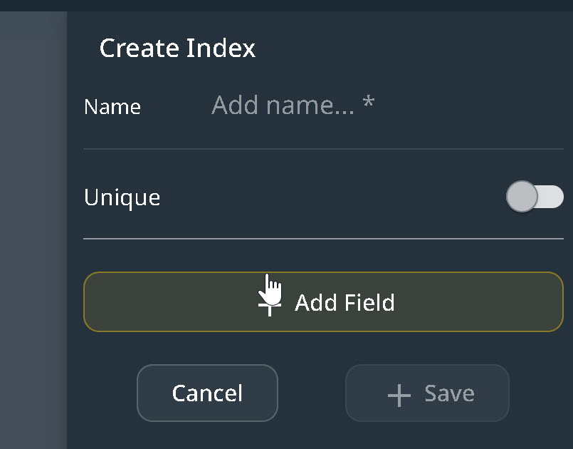
When creating an index, you can designate it as unique. A field indexed as unique will ensure that no two entity instances have the same value in the field associated with the index. Adding a duplicate value to such a field at runtime will result in a runtime error.
Add entity fields to the index.
To create a composite index, you can add multiple fields. Adjust the sequence of these fields by dragging them, as the order can be crucial for querying and sorting operations.
Consider this example involving a composite index:
In an e-commerce application, purchases are tracked in a database, each with fields such as ‘date‘ and ‘totalCost.’
If you want to retrieve all purchases between Date A and Date B and within a cost range of X to Y, a composite index encompassing both ‘date‘ and ‘totalCost‘ can enhance the query’s performance. If questions frequently specify a specific date with a range of costs, then ‘date‘ should be the first field in the index, followed by ‘totalCost.’
Also, if the primary requirement is to sort the results by ‘date’ and then by ‘totalCost,’ then the ‘date’ field should precede the ‘totalCost’ field in the index.
Additionally, if there’s often a need to query just based on the ‘date‘ without specifying ‘totalCost,’ having ‘date’ as the first field in the composite index would also be beneficial, as databases can effectively use the index’s “prefix” for such queries.
Diagrams #
Wizzdi Cloud supports multiple diagrams for large domain models.
Click “+” in the bottom left corner to add a new diagram.
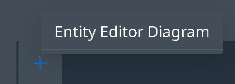
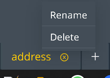
Diagram Name Context Menu (right click)
Access the context menu by right-clicking on the diagram name to rename or delete a diagram.
The context menu is active only for the currently selected diagram.
Rename an Entity Diagram
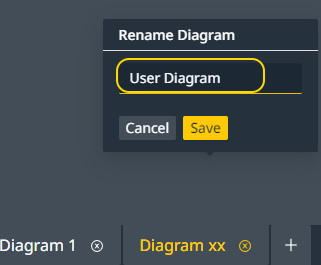
Rename a diagram
Deleting an Entity Diagram
You can permanently delete the selected diagram from the context menu. This action is irreversible and cannot be undone.
Entities and Enums created in the diagram persist and can be imported into a new diagram.
Closing an Entity Diagram
You can close a diagram from #2 here.
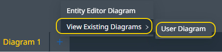
When a diagram is closed, it can be reopened from the Add Diagram button.
When a diagram becomes too large, you can create a new one and transfer or duplicate some entity shapes onto the new diagram. However, note that only the entity’s delegate on the diagram will be copied, not the entity itself. This makes it easy to divide large diagrams into smaller ones.
To connect entities on separate diagrams, you must first move or copy one of the entities to the diagram where the other entity is located. After the entities are connected, you may remove one of the entity shapes from one of the diagrams to simplify it.
Moving, removing, and copying entity shapes can be done from the three-dot menu on the entity shape.